Lisa/S Progress April 08 2014
Hi everyone,
We would like to bring you up to date with the current status of the Lisa/S progress. We know it is long overdue and we promise to post updates more often from now on.
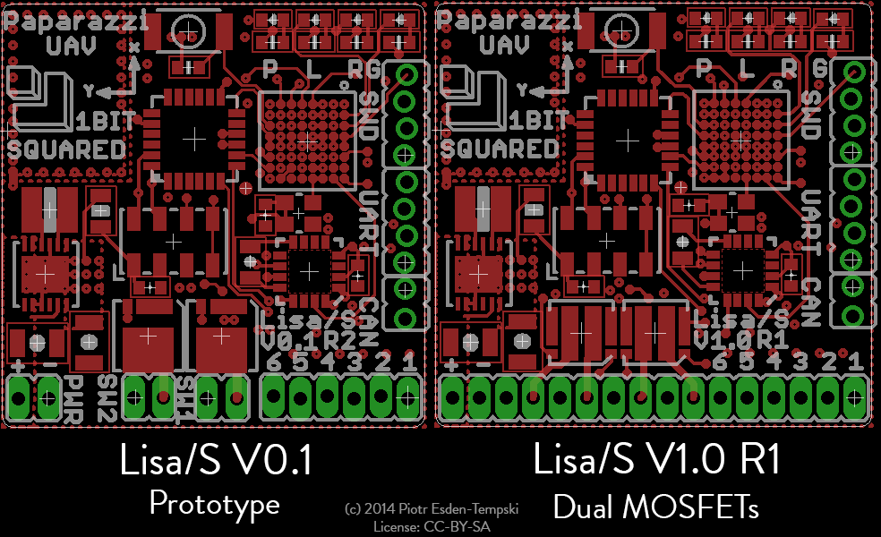
As you might know, the Lisa/S you have seen on pictures and in press articles, was the first prototype version 0.1. Since last year we have learned a lot about the hardware and focused on a few places for potential improvement. We wanted to make these improvements before we produce a few hundred of them, as we want to provide you with the best product possible. Sadly this added a delay to our production schedule, but we think that the improvements are worth it. We are very close to sending off the boards for manufacture, and we will update you here as soon as we hear back from our manufacturing partners.
In the mean time let us tell you a little about the improvements that we were working on in the past few months. For the impatient ones among you, here is a brief list of improvements. For a more in depth analysis, read on if you want to hear the whole story:
- PCB manufacturing improvements
- Provide 4 MOSFET switches to support brushed nano quadrocopters out of the box
- Add backup super capacitor to the GPS for faster satellite reacquisition when swapping batteries
- Add m2 mounting holes for accurate, reliable and maintainable mounting on standard airframes
- Panelization
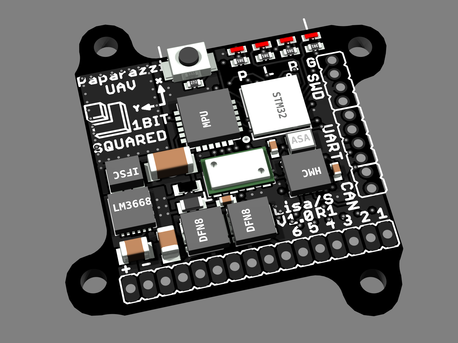
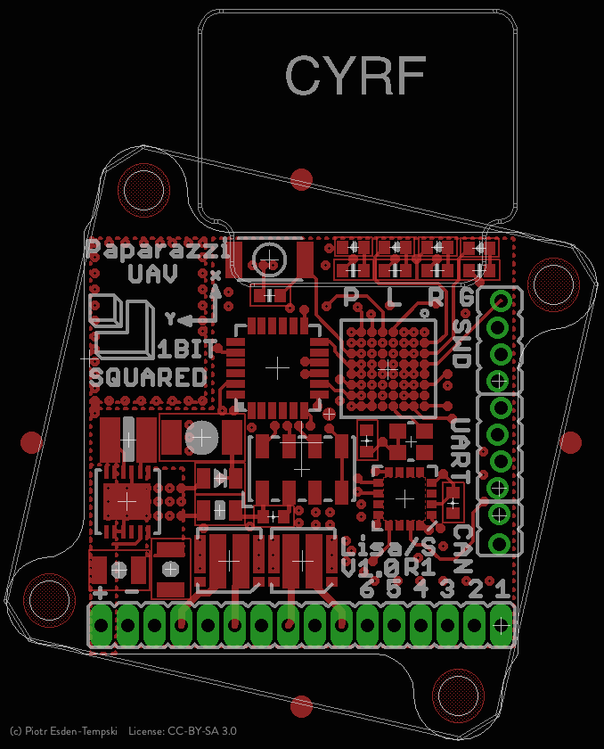
And this is a rendering of the board including those changes:
1) PCB Manufacturing improvements
Let us start with the first and probably the one that turned out to be the easiest change. All traces on the prototype board were 0.1mm wide. From the standpoint of increasing manufacturing yield, the designer needs to reduce the amount of tiny features. Consequently, we changed all possible traces and spaces to 0.15mm (6mil). The only area that we could not do anything about is the STM32F1 0.5mm pitch BGA footprint. But we hope that our PCB manufacturer will appreciate the effort and it will speed up the board manufacturing.
2) Provide 4 MOSFET switches
Obvious platform choices for Lisa/S are, besides the nano helicopters, the brushed motor quadrocopter airframes. The prototype design for the Lisa/S was motivated by a helicopter so we only incorporated two MOSFETs (solid state switches) to actuate the main and tail rotors. If you wanted to mount Lisa/S on a quadrocopter you would have to add two more MOSFETs or use dedicated motor controllers.
This seemed like a big hurdle and a waste of weight. Being able to incorporate 4 MOSFET's on the board would improve the experience of using the autopilot quite a bit. Lisa/S was already highly integrated so it took us some time to come up with a solution. After doing some research, we realized that the Fairchild MOSFETs that we are currently using have a sister product in a very similar format providing two switches per package.
Having two separate MOSFETs means compromising some of the current handling ability of the circuit. That is OK because quadrocopters use less power per motor than a helicopter, and if used on a helicopter we can wire two or more MOSFETs in parallel to drive a motor.
Another hurdle was the fact that if we add two more switches we also should provide two more motor connections. In V0.1 we had two pins per motor providing power and switch, making wiring reasonably simple. We wanted to add two more sets of connectors to the board to make the wiring simple but that forced us to increase the board width by 0.65mm. The alternative would be to add only the switch pins and as a user you would need to wire up one of the motor pins directly to the battery. We came to the conclusion that the increased width of the board from 20mm to 20.65mm is an acceptable sacrifice for the improved simplification of the wiring scheme.
3) GPS backup super capacitor
While testing the Lisa/S prototypes we realized that we are swapping batteries on the board quite often. As you might know most GPS setups have a backup battery or super capacitor to keep some of the data about satellites stored between power outages. When a GPS has to boot up after having no power at all, it is called a "cold start". While booting up with a backup power source is called "hot start". A cold start takes about 29 to 30 seconds to acquire enough satellites to get a 3D fix. A hot start takes only about 1 to 2 seconds to reacquire the satellites it lost due to the power outage. This is a significant difference that we decided to address.
We found a tiny 11mF super capacitor 1210 package. According to the datasheet the MAX-7Q module we use on Lisa/S draws 15µA from the backup power source. That means assuming we charge the capacitor to the nominal 3.3V we theoretically get 0.011F * 3.3V = 0.0363A/s out of it. This means we can keep the module on backup power for 0.0363A/s / 0.000015A = 2420s = ~40.3min in ideal conditions. Even if the actual number is 10 or even 5 minutes we have more then enough time to change the battery between adjacent flights.
By moving around a bunch of traces and parts, we found a spot on the board for the supercap and charge diode near the power supply area.
4) Add mounting holes
We also decided to work on the mechanical mounting of the board, that many of you inquired about. This turned out to be a much more challenging than anticipated. Most of the nano sized frames do not use screws to mount their control boards. They instead use double sided sticky foam. We realize that is a messy and unreliable solution. Definitely if you are doing development and want to be able to be able to swap the autopilot with ease, or make sure that the board is at an exactly defined angle to the body of the aircraft. That means we need to add mounting holes. From past experiences, we know that mounting holes are something you have to think about very carefully, since you will likely set a "standard", and a poor choice will cause a lot of headaches in the future.
As mentioned before, we looked at what others are doing to mount their control electronics. One nano quadrocopter frame that is widely available and very affordable is the Ladybird and its clones. It has rubber screw mounts for the board, spaced 20mm in a square. Due to its availability and modularity we decided that we should try to be compatible to that airframe. It is exactly the dimension of Lisa/S, so to add those holes directly to the board we would need to move a lot of parts on the board, and probably sacrifice signal integrity. We considered adding holes in a wider square of 24mm x 24mm and using an adapter board, but that would add additional weight to the setup that we did not want to sacrifice. You can see below, the evolution of different hole mounts.
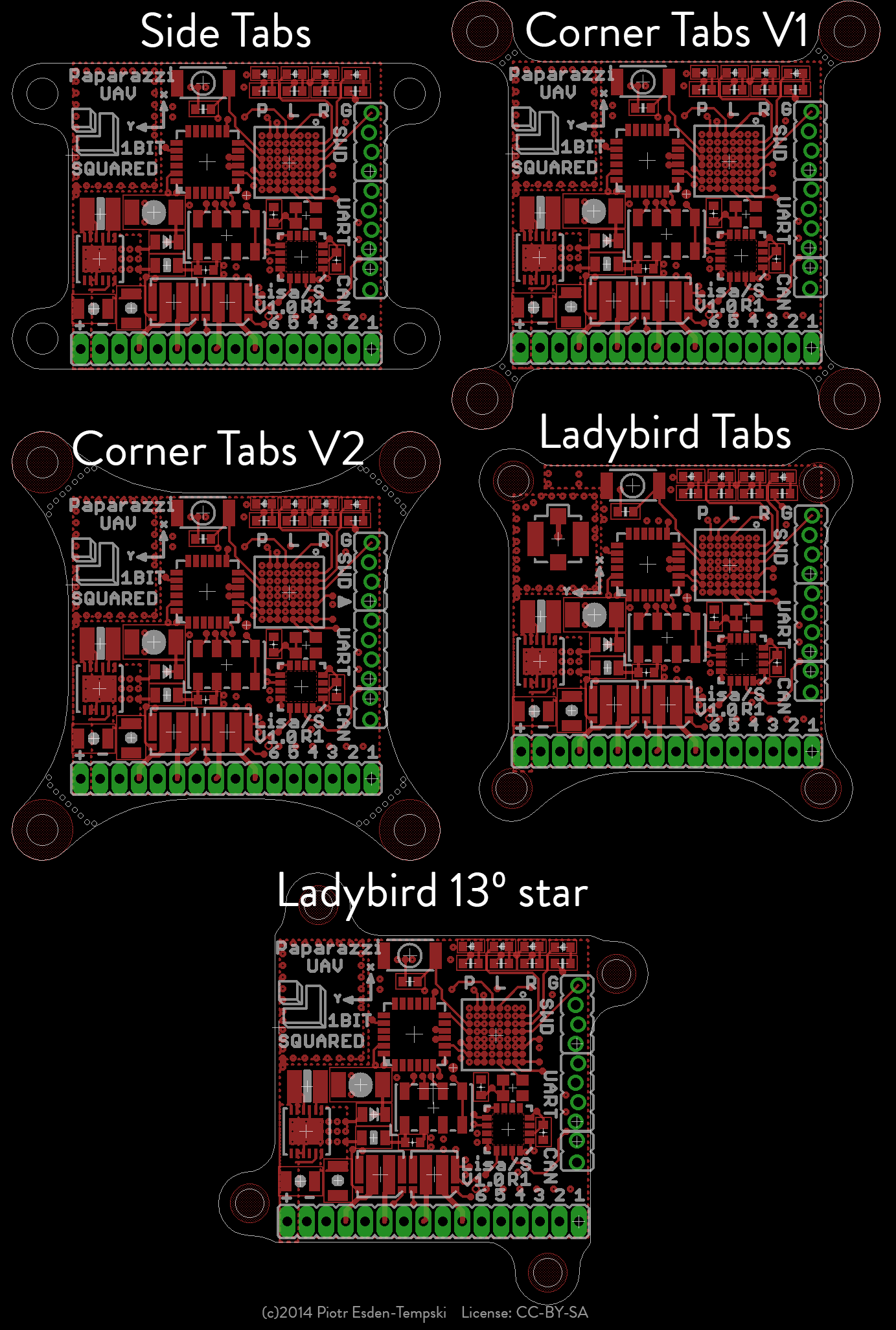
We decided on a compromise. We added 20mm x 20mm mounting holes rotated by 13º around the center of the board. Paparazzi UAV has the body to IMU rotation parameter in the airframe definition. We can use that to compensate for the rotation in software. Also by having the holes offset, they can be on tabs that are v-scored along the edge of the board. This makes it possible to snap them off in case you don't need the mounting holes and would rather save the weight.
5) Panelization
After all those improvements we decided to send the design to our assembler to ask for input. I am very happy we did as they had a few very good suggestions.
- Arrange the panel in a 3 x 4 matrix with rails on the 4 sides
- Split the matrix in two 3 x 2 sets and mirror one of the sets to have an open book format
- Add fiducials to every board
- Add soldermask between copper pads
5a) Panelization - arrange Lisa/S in a matrix
This is a compromise on the number of boards assembled in one machine load. The 3 x 4 matrix arrangement results in a panel size that is reasonable to handle by the solder paste dispenser, pick and place machine and re-flow oven, without making the panel costs too high. As we mostly produce small batches by industry standards optimizing the panel size is an important step.
5b) Panelization - split the matrix
An additional advantage of arranging the board in a 3 x 4 matrix is that it now has a line of symmetry. If you arrange the board so that half of the panel exposes the top of the boards and the other half exposes the bottom of the boards you will save time and money during assembly. Your assembler will not need to reconfigure the machine for top and bottom assembly of your board. Confused? Let me try to explain.
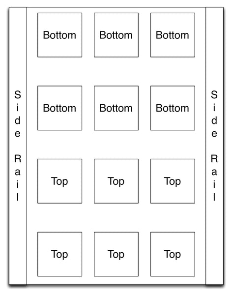
The stencil as well as the pick and place machine setup can have top and bottom sides set up. In the first run of your board, half of the boards get their top side populated and soldered and half the bottom. Then the board is flipped around the center symmetry line and run a second time through the assembly line. The boards that got the top populated in the first run will have their bottom side populated and vice versa.
It was actually an interesting challenge to create an open book formatted panel. We are using Cadsoft Eagle and GerbMerge with a bunch of gnu makefiles to generate our gerber files. The first idea was to use the mirror-board.ulp in Eagle. This would mean that if we make any changes to the master pcb design we will have to remirror everything. Additionally the mirror-board.ulp can not handle blind vias. Meaning we would need to convert all the blind vias into regular vias, mirror the board, and convert the vias back into blind ones. This was a lot of manual work every time we do a minor change, or we would have to dive into the ulp and teach it to deal with that automatically. On top of that Eagle does not swap internal copper layers when you tell it to mirror things.
The solution to all of that ended in the gerber file generation step. We just added another set of gerbers that are mirrored and renamed into <boardname>_m.<tld>, We then just had to add it as a second job into the gerbmerge configuration and voila.

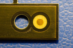
5c) Panelization - fiducials
The assembler also asked for more fiducials. Fiducials are the small round copper markers that you might have previously seen on PCB's. They are used in PCB assembly machines as visual reference markers. The assembler said that it would be nice to have fiducials on the board itself. We already had some fiducials on the panel mounting rails, and those are quite big. To see how small we can go we tried to find some recommended fiducial design guidelines. Based on a recommendation document we found the minimum size should be 1mm in diameter. Sadly there is no space on the board for a 1mm copper circle with another 1mm border around it, with no features present. This is why we ended putting the fiducials on the panel attachment tabs. We sent the changed design to the assembler and we hope that will be good enough.
5d) Panelization - soldermask
The assembler also pointed out that some of our footprints don't have soldermask between copper pads. This may cause the solderpaste to create bridges in reflow. We went through all the footprints and compared them to the recommended footprints in the corresponding datasheets and decreased the opening to the minimum recommended by the JEDEC standard.
Final words
As you can see, we have been quite busy providing you with the best product possible. We also hope that by now you understand why the boards are not in production yet. But as far as we can tell, we do not have any more items on our TO-DO list, and we will be sending out the PCB panels to our manufacturer this week. This means that if everything goes well we should be sending the final boards to those of you who pre-ordered the boards by the beginning of next month. We also promise that from now on we will continue to write regular updates here in the blog so you can follow along in our progress. Thank you for the support.
If you have any questions or comments, drop us a line in the contact form or in the comments below.
Regards,
Piotr Esden-Tempski and the 1 Bit Squared team.


